a bender's guide
[circuit-bending] ![]()
a bender's guide
|
[potentiometers] |
|
| [circuit bending] [introduction] [tools] [parts] [exploring the art] [how it works] [direct wiring] [potentiometers] [capacitors] [photo resistors] [solar cells] [leds] [humidity sensors] [body-contacts] [reset switch] [line outputs] [other techniques] [cautions] [closing words] |
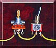
Instead of switches,
potentiometers (variable resistors) can be soldered in the middle of the pairs of
connections. In many cases this will allow the adjusting of the new effect with the turn
of a dial. Potentiometers, like non-adjustable common resistors, come in a variety of
values measured in ohms of resistance. Experiment with different values to learn their
effects. Potentiometers usually have three soldering points, or lugs. Solder your two
wires so that one connects to the middle lug and the other to one of the outside lugs.
Which outside lug you choose depends on what you want the effect to sound like as the
potentiometer's dial is turned in a pre-determined direction. Example: The volume control
on your stereo is a potentiometer. If you were to reverse its outside lug wiring the
volume would go DOWN when you turned it up (clockwise). |
|
 |
||
|
||
| [continue] | ||
| [1] [2] [3] [4] [5] [6] [7] [8] [9] [10] [11] | ||
| [12] [13] [14] [15] [16] [17] [18] [19] |