|
| ||
| The Art of the Creative Short
Circuit by By Qubais Reed Ghazala Electronic Musician, Jan 1, 2003 | ||
Not that long ago, a short circuit in audio electronics was considered to be only one thing: destructive. But nowadays, an audio short can function as a constructive as well as a creative element. The creative short circuit, or the technique that I call circuit bending, is a form of hardware hacking or modding, but with two important differences. First, whereas hackers usually know something about electronics, you don't need any real knowledge of electronics to circuit-bend. Second, while most people hack an instrument with a particular goal in mind — such as increased frequency range or cleaner outputs — the circuit bender works improvisationally and has no idea where the trail will lead. In circuit bending, the instrument shapes itself by telling the bender what it can do. In this way, circuit bending has turned the electronic circuit into an immediate “canvas”; a circuit is accessible at that moment to everyone for the creative act. No theoretical knowledge is required, and on the first occurrence of experimentation a one-of-a-kind instrument is created.
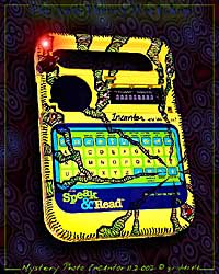
Before I go into detail about how to build an Incantor, which is my design for bending a Speak & Spell, a Speak & Read, or a Speak & Math toy, I will begin with a general primer on circuit bending. Circuit-bent instruments can sound like just about anything, real or unreal. To hear what a typical Incantor sounds like, check out the audio examples online. Circuit-bent instruments can retain their original voices, especially if the bender makes only modest adjustments in timbre or envelope. It is the deep end of circuit bending, however, that most people find enticing. Many circuit-bent instruments produce fascinating aleatoric music under the “clear illogic” of circuit bending. Here we seek to embrace, rather than tame, the chaos. CAUTION BEFORE YOU BENDAlthough circuit bending is simple, it is a try-at-your-own-risk endeavor. Never attempt the following procedures on anything that is plugged in to an electrical outlet — not even through a wall wart. You want no relationship whatsoever with the power mains, secondary coil or not. Transformers can fry and shunt, and wall-wart electronics are often shoddy. Circuit bending is only for battery-powered circuits of 6V or less. Never bend a circuit that you'll miss if it fries. Bending is more for the abandoned circuit — like the sound toys that you see in thrift shops — than it is for your vintage stompbox from the '60s. Anyone can destroy a circuit in a moment with the wrong connection. But don't let that stop you; it's more likely the result will be unusual audio artifacts. Soldering is an important aspect of circuit bending and is fairly easy to learn. For this article, I will assume that your soldering skills are such that you can make quick and precise connections. Quick, because some components can be damaged by the heat of excess soldering, especially since the bender may at times find it necessary to solder directly to integrated circuit (IC) pins leading to delicate electronics inside the IC. Precise, because, as in the example of IC pins, clearances can be minimal. The danger is that you may create an inadvertent “solder bridge” between IC pins (or other tightly spaced metals, such as printed circuit traces, component leads, and so on) that were not meant to be soldered. Practice soldering until you feel comfortable, quick, and precise. In addition, practice safe soldering. Vent smoke away from you, wash your hands thoroughly after soldering to remove lead residues, and wear safety glasses. If you're new to the field, I recommend that you read an electronics book geared toward beginners. Forrest M. Mims's books Getting Started in Electronics and the Forrest Mims Engineer's Note-book (both available at Radio Shack, among other places) are good to begin with. These guides explain useful terms and cover how various components — switches, potentiometers, resistors, capacitors, and LEDs — operate. The books also cover the basics of circuit construction and lead into more advanced subjects. GENERAL BENDINGBegin by finding some good-sounding battery-powered musical toys, such as keyboards or talking games. You'll find these clogging the isles of many second-hand stores, as well as at flea markets and garage sales. Bring a supply of batteries when you shop — four each of AA, C, and D sizes — so you can try the devices before you buy them. Open the toy you've selected in order to expose its circuit, but keep the batteries in place. At each end of an alligator-clip test lead, clip a small metal jeweler's screwdriver (see the sidebar “Circuit-Bending Toolkit”). While the circuit is making a noise, and with your safety glasses on, press one of the screwdriver tips to a circuit trace (see the sidebar “Circuit Precautions”). With the other screwdriver tip, touch the various traces while listening for interesting changes in sound. Every time you find an interesting sound, use a marker to note the connections on the board. Search the board in this way until all possible connections have been tried. Once you're finished, move the stationary tip to another trace and start again. Repeat this procedure until you have searched the entire circuit. Once you have fully explored the circuit and marked the board, you can implement your newly discovered connections using any of the following parts. Direct wiring/switchesBetween each pair of points, solder a wire with a toggle switch in the middle. Next, mount the switch on the case somewhere. Use the simple mini toggle switch known as Single Pole, Single Throw (SPST). PotentiometerAdd a potentiometer (variable resistor) to the new circuit. That will allow you to adjust the effect in interesting ways. Potentiometers, like nonadjustable common resistors, come in a variety of values and are measured in ohms of resistance. Experiment with different values to learn about their effects. Potentiometers usually have three soldering points or lugs. Solder your two wires so that one connects to the middle lug and the other to one of the outside lugs. (Which outside lug you choose determines whether you turn the dial clockwise or counterclockwise to initiate the effect. You may need to experiment.) CapacitorsTry adding capacitors to obtain timbre changes and pulsing effects. But be aware that larger electrolytic capacitors can hold a charge and zap you. Even though you will rarely see these capacitors in the typical instruments you'll bend, you should read up on the subject of capacitors if you're not familiar with them. Photo resistorsThese are light-sensitive cells that have two wire leads. They convert light into electrical resistance and have the same effect on a circuit as a potentiometer. But instead of turning a dial to vary the resistance, you vary the amount of light reaching the photo resistor. LEDsIn circuit bending, light-emitting diodes (LEDs) are usually used as low-voltage light sources. You may find that an LED will glow or pulse when placed between circuit points. This can serve as a function indicator. For example, an LED wired to the speaker leads may indicate the envelope of the sound by flashing with the intensity of the sound waves. LEDs may also affect the sound of the circuit, depending on where they are connected. LEDs are “polarized” components; if they don't glow when connected between promising points on a circuit, try reversing the leads. If they still don't glow, there is not enough power available to activate them. CAUTION: with your goggles on, test an LED's connections very briefly at first. Overpowered LEDs will glow too bright or off-color at first, and may then finally shatter. Body contactsBody contact is an interesting part of circuit bending but by no means crucial. Among the countless designers who have used body contact with electronic circuitry are Michel Waisvisz with his Crackle Boxes and Donald Buchla with his capacitance keyboards. Although I've used the body-contact system on these low-voltage circuits for 35 years without noticeable harm, I'm not about to tell you that it is without risk. (I have been assured by experts that the voltage levels involved are nothing to be concerned about; the flow is minimal and external/dermal.) If, however, the body-contact system scares you, don't do it. Body contacts are simply metal contacts, such as drawer knobs or finials (threaded brass balls that attach to light fixtures), that are wired to the pair of circuit-bending points. Each of the two circuit points goes to its own body contact. Nothing is wired between them: no switches, no potentiometers, and no sensors. These contacts, when mounted on the instrument's case, are meant to be bridged by the player's body, making him or her a variable human resistor. Vibrato and tremolo are easy to achieve using body contacts, but you might also find contacts that will affect tone and sound and/or sequence triggering. Before you begin, search the entire circuit with a volt-ohm meter. If you find areas that are more than 6V, avoid them in your body-contact searches. If you ever feel the electricity of a body contact, abandon it or find an alternative. After verifying a low-voltage board with your volt-ohm meter, search the circuit as before. This time, however, hold a screwdriver in each hand instead of using the alligator-clip test lead (see Fig. 1). While listening for changes in the sound, mark the responsive connections for body contacts. Next, wire a metal object to each point and attach them to the case. By touching these contacts, the player changes the sound and becomes an integral part of the circuit. Again, it must be stressed that you should attempt the body-contact method only with battery-operated audio devices that use 6V or less. Never attempt this procedure using a device that is plugged in to an AC wall outlet. Reset switchWhether it's your PC or a Speak & Spell, systems crash. In order to reset a bent circuit, install a “normally closed” (NC) push-button switch to interrupt the voltage supply from the battery compartment. Begin by searching for a battery wire to clip. If you cannot locate one, you will have to study the circuit and find a power-supply trace on the board to cut. Next, solder the switch with a wire to each side of the cut trace. To find an easier soldering point for the wire, follow the trace to the next component or scrape the trace clean on either side of the cut and melt a small blob of solder onto the trace. Then, solder the wires to those blobs. Be sure to mount the switch in a place where you won't hit it accidentally. Line outputsLine outputs are important if you want to experience the full potential of an instrument's frequency range (which often far exceeds the capability of the built-in speaker). Adding a line output also opens the unit up to external signal processing. A suitable line output can usually be derived from the wires going to the speaker. Simply mount the output jack of choice on the case and solder new wires to it that come from the speaker terminals. Then, plug the instrument in to a small amp to check the output level. Slowly turn the amp up. If the signal is too hot, add a trim pot to one of the wires going to the new jack you installed and adjust it accordingly (1 Mž will probably work). Replacing componentsIn addition to creating new circuit paths, you can replace the components on a circuit with ones of a different style or value. For example, a standard resistor on a circuit board can often be replaced with a potentiometer or a photo cell (both are variable resistors). If the component is a resistor that sets the pitch of a voice (which is common), that voice now becomes tunable, allowing you to change frequency with the turn of a dial or the shifting of light. Similarly, you can replace a potentiometer with a photo cell. Motion sensors — such as mercury, boxed ball, and tilt switches — can be wired into small devices for dance or gesture-driven instruments. To address space limitations when mounting new controls, completely remove the circuitry from its original housing and install it in a new enclosure. Or, construct a remote-control panel to hold the new switches and dials and connect it to the original circuit by means of a braided or ribbon cable. For those situations in which there is limited space in which to solder — as with short component leads and IC pins — study the circuit to see if the area you wish to solder to is connected to a trace on the board that's easy to get to. A resistor lead within a circuit that is hard to get to, for example, might connect with a printed circuit trace that emerges, with full access, on the other side of the board. Soldering to a trace that connects to the desired component elsewhere is the same as soldering to the component lead itself. This technique can be a real problem-solver for tight spaces. Many additional components can be wired into the path of the pairs of circuit-bending points. But the above will get you started on your way to discovering hundreds of possibilities as well as toward understanding wider concepts. TEST BEFORE YOU SOLDERYou can use a modified test-lead system to quickly test the various components between the pairs of contact points. Such a system consists of the two screwdrivers as before, two alligator-clip test leads instead of one, and the component to be tested (potentiometer, photo cell, LED, and so on). Clip a screwdriver at one end of each test lead. Next, between the empty ends of each test lead, clip the component to be tested. The screwdrivers again serve as probes with which to search the circuit, but now you are sending the signal through the component that is clipped between the two leads. The wiring procedure begins when you determine how many pairs of connections you have, the types of components you want, and how many you'll need. Then, you can decide how and where they will be mounted on the device's case. (Remember to check for clearances so that the backs of the new switches don't hit internal parts when the unit is reassembled). Next, drill the holes, mount the switches, and solder the pairs of circuit-bending connections through their respective switches. ADVERSE EFFECTSYour new circuit paths may have no adverse effect upon a circuit when they are switched on by themselves. Problems may occur, however, when some of the paths are used simultaneously. For example, the volume may decrease or drop out altogether when two or more switches are on. Be aware of such switching combinations; avoid them or modify the wiring behind them by finding another pair of points to wire one of the switches to. Retest the device. Feel the ICs, resistors, and other components on the circuit board as you test the connections. If you make a connection that causes a component to become unusually hot (some components warm up a bit normally), it's a good idea to avoid that connection. Good circuit-bending connections create unusual audio behavior without taxing the circuit or draining power, and without destroying the electronics. There is no way to experience all the switching combinations as the new wiring is being charted on the circuit board. Not until the instrument is complete can the designer fully explore it, because it is not until then that all of the connections and new controls are in place and can finally be combined. At that point, the instrument reveals itself in ways not evident during the initial, one-effect-at-a-time discovery process. This is a wonderful moment. INCANTOR ENCOUNTERThe Incantor streams shattered phonemes, bridged with unusual tones and noises, that combine with recognizable words as the speech synthesizer's linear predictive coding lattice is rearranged by the creative short circuit (see Fig. 2). It is possible to set loops on an Incantor. That provides a means of control within the chaos and allows you to divide the abstractions into approachable measures. I also add a master pitch control so that the sounds can be clocked very slowly. You can induce a real-time vibrato using body contacts. Those usually take the form of small metal balls wired directly to circuit points. When you touch the contact points, changes occur within the circuit that might adjust pitch, volume, or timbre or initiate other circuit activity such as triggering a voice or incrementing a loop. You should become familiar with how the Speak & Spell works before you begin to bend it (see the sidebar “Parts for the Incantor”). There were many different circuit boards in the Speak & Spell over its manufacturing run (see Fig. 3). While the instructions here show one of the most common boards, yours might not match. Just dive in with the general bending advice provided earlier and use Fig. 3 as only a very general guide. (You can e-mail me directly with questions if your board doesn't match the one presented here or if you want to inquire about a prebuilt Incantor.) After removing the batteries, remove the two screws at the bottom back of the instrument (you might need a Torx driver). Next, remove the back of the unit by prying the locking tabs in the four square holes inward with a screwdriver blade. Some people leave the clear gray display lens intact, while others pry it off. That's up to you. Steering clear of the keypad and circuitry, drill three ⅛-inch pilot holes for the toggle switches and one for the pot (you will need to locate a space where that will fit). It's convenient to drill the hole for the push-button reset switch in the void to the bottom-left of the battery compartment, below where the black battery wire runs (be careful not to hit it by accident). The pilot holes can be enlarged with a hand bore, the tapered blade of some scissors, or a spherical burr bit. Mount all components. Wire the push-button reset switch in the middle of the black battery wire. That switch cuts power to the circuit when pressed. Remember, the reset switch is an NC switch: it breaks, not makes, the circuit. Wire the pitch pot to the circuit points as shown in Fig. 3. One wire goes to the middle lug of the pot, and the other wire goes to the lug counterclockwise from the middle lug (as viewed from the back of the potentiometer). Note that turning this pot down all the way (fully counterclockwise) will crash the circuit. When you get into the speed range where the fluorescent display begins to flutter, you're near a crash. (You can install a trimmer pot to limit the low-end of this range, in order to avoid crashing, if you like.) Wire the group of two bending switches. These are the “bends” that turn the output into unusual audio sequences. Finally, wire the remaining loop toggle switch (see Fig. 4). TESTING PROCEDURESNow it's time to load the batteries. Hold them in place with a strip of tape and begin the testing procedure. Press the reset switch immediately if the circuit crashes in any of the following:
The Speak & Spell/Incantor has a built-in ⅛-inch headphone output jack, so you can immediately plug the instrument in to your audio-playback system. Now you can add effects or sample the instrument and layer the voices. Build several Incantors to fade in and out and combine live with a mixer. Or just sit back with an Incantor in your lap and explore. MAKING CONNECTIONSWith the Incantor, we've seen a little of what circuit bending can do to a human-voice synthesizer, a machine whose sound banks are loaded with the building blocks of speech. Imagine bending a circuit that has banks filled with the sounds of musical instruments instead. What about circuit bending a sampler? The circuit-bent Casio SK-1 is a mind-blower. Your sample is recomposed, layered, time-shifted, deconstructed, and combined with other sounds within an often dreamlike rise of odd musical waves. Once you grasp the bizarre sensibilities of this art form and the highly unusual music that results, you will find yourself poised on the brink of a new world. You have literally thousands of experimental instruments to discover within derelict circuits that can be purchased for next to nothing. I've been bending for 35 years and have barely scratched the surface. Today's abandoned circuits are often quite advanced and hold great bending potential. This is definitely an excellent time in which to circuit-bend! Qubais Reed Ghazala's work can be found in the permanent collections of the New York City Museum of Modern Art, the Guggenheim, and the Whitney, and in the possession of Tom Waits, Peter Gabriel, King Crimson, and Faust, among others. Ghazala's series of articles entitled “Circuit-Bending and Living Instruments,” published in Experimental Musical Instruments between 1992 and '97, introduced circuit bending to the world. His Web site is http://www.anti-theory.com/, and he can be reached at anti_theory@fuse.net. CIRCUIT PRECAUTIONS
Besides protecting yourself and the components that you add to the circuit, there are precautions you can take that will protect the circuit itself. While exploring the circuit with the test lead, make the connection very briefly at first. Always exercise caution while near the power supply. Voltages here are often higher than elsewhere on the board and can zap a chip if jumped to a pin “downstream.” Forget about that connection if you witness:
CIRCUIT-BENDING TOOLKIT
A custom circuit-bending console can be built in the form of an elaborate substitution box. Such a box may contain selectable components (selected with multiposition rotary switches) to run the circuit-bending paths through, including resistors, capacitors, potentiometers, sensors, and LEDs. Like a resistance substitution wheel, a circuit-bending console would be another two-lead device that could be clipped between two circuit points and adjusted to observe audio changes within the operating circuit. PARTS FOR THE INCANTOR
(1) Speak & Spell. These can usually be found online (often on eBay or other auction sites) as well as at second-hand shops. (1) Small panel-mount 500K potentiometer with mounting hardware. (3) Panel-mount mini toggle switches (SPST) with mounting hardware. (1) Panel-mount mini push-button switch, NC (normally closed), with mounting hardware. (1) Spool 25- or 30-gauge insulated “wire wrap” wire for the new “bends” you'll solder in place. | ||
© 2003, Primedia Business Magazines and Media, a PRIMEDIA company. All rights reserved. This article is protected by United States copyright and other intellectual property laws and may not be reproduced, rewritten, distributed, redisseminated, transmitted, displayed, published or broadcast, directly or indirectly, in any medium without the prior written permission of PRIMEDIA Business Corp. |